System
The System pages provide comprehensive information about the Genius Gateway's hardware status, performance metrics, diagnostic tools, and firmware management capabilities.
System Status
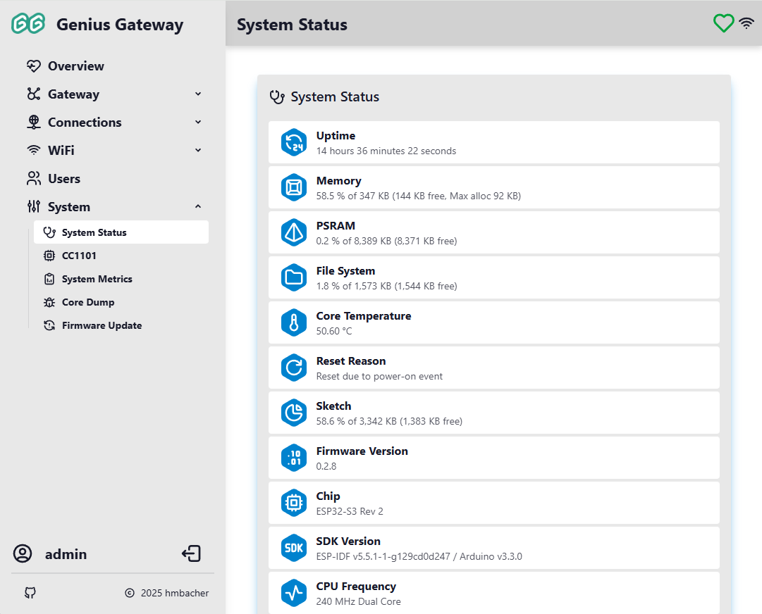
The System Status page displays detailed information about the gateway's current operating state, hardware configuration, and resource utilization. This information updates in real-time via WebSocket connection.
System Information
The status page displays a lot of self-explaning system related information.
Device Management Actions
At the bottom of the System Status page, several management actions are available:
Restart
Performs a software restart of the device. The device will reboot and reconnect to the network automatically.
Factory Reset
Resets all settings to factory defaults, including: - WiFi configuration - User accounts - MQTT settings - Device and alarm line configurations - All other custom settings
Permanent Action
Factory reset cannot be undone. All configuration data will be permanently erased. The device will restart with default system settings (from factory_settings.ini) and not Genius PLus X related configuration.
Radio (CC1101)
The CC1101 page provides runtime SPI pin configuration for the CC1101 radio transceiver. This page is only accessible to administrators.
Top-Bar Radio Indicator
The radio status is reflected by a persistent icon in the navigation bar that links to this page from anywhere in the interface:
| Icon | Meaning |
|---|---|
| Loading — radio status not yet received | |
| Radio listening (RX) — normal operating state | |
| Radio transmitting (TX) | |
| Radio initializing | |
| Radio error — check pin configuration | |
| Radio not configured |
Pin Configuration
The SPI bus and GDO signal pins used by the CC1101 transceiver can be changed at runtime without reflashing the firmware. Pin settings are persisted on the gateway and survive reboots.
If the board has predefined wiring presets, a Wiring dropdown lets you select one and fills in all pins automatically. Select Custom to configure each pin individually.
| Pin | Role |
|---|---|
| CSN | SPI chip select (active low) |
| SCK | SPI clock |
| MOSI | SPI data from ESP32 to CC1101 |
| MISO | SPI data from CC1101 to ESP32 |
| GDO0 | Packet signal — asserted when a packet has been received |
To change pins:
- Select a wiring preset or choose Custom and pick a GPIO for each pin. Reserved GPIOs are highlighted in red and cannot be selected; strapping pins are highlighted in orange as a caution
- Click Test & Save — the gateway probes the CC1101 over the new pin assignment and saves the configuration if the self-test passes
- The top-bar radio indicator updates to reflect the new state
Pin conflicts rejected
Assigning the same GPIO to two different pins is blocked before any change is applied.
Existing installations unaffected (Genius Gateway hardware only)
If no pin configuration has been saved, the firmware uses the compile-time defaults from platformio.ini. Upgrading from an older firmware leaves pin assignments unchanged until you explicitly apply new ones via this page.
System Metrics
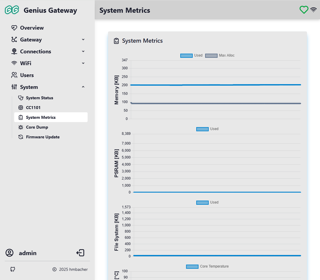
The System Metrics page provides real-time graphical visualization of system performance over time.
Metrics collection begins when the web interface connects to the device and continues while it remains open, with data displayed as line charts. Charts update automatically as new data arrives via WebSocket.
Performance Monitoring
Monitor these metrics to identify resource constraints, memory leaks, or thermal issues. Sudden spikes or trends may indicate problems that need attention.
Memory (Heap) Usage
Line chart showing:
- Used: Amount of heap memory currently allocated (primary line)
- Max Alloc: Maximum contiguous block available for allocation (secondary line)
Y-axis scale adjusts to the total heap size.
PSRAM Usage
Line chart showing PSRAM utilization over time.
Info
This chart is only displayed if PSRAM is available on the device.
File System Usage
Line chart showing the amount of flash storage used by the file system over time.
Core Temperature
Line chart showing the ESP32 chip temperature in degrees Celsius over time. Useful for monitoring thermal performance and detecting overheating conditions.
Core Dump
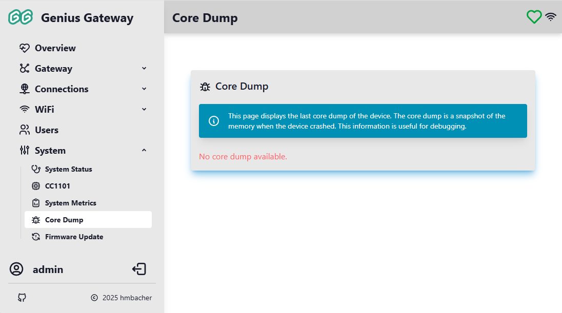
The Core Dump page allows you to download diagnostic information captured when the device experiences a crash or exception. This data can be helpful for debugging firmware issues.
Core Dump Information
A core dump is a snapshot of the device's memory at the moment of a crash, including:
- Register states
- Stack trace
- Memory contents
- Exception cause
Downloading Core Dumps
If a core dump is available:
- Click the Download Core Dump (coredump.bin) button to download the core dump file to your computer
- This file can be analyzed using ESP-IDF tools to determine the crash cause
Info
If no core dump is available, the message "No core dump available." is displayed.
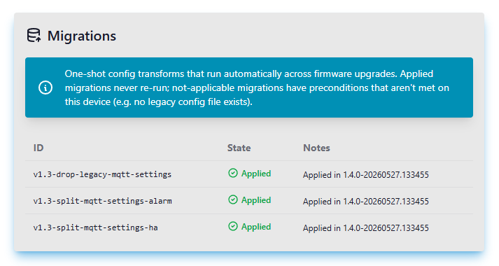
Migrations
The Migrations page shows what automatic config upgrades the gateway has performed across firmware versions. When you flash a new firmware, the gateway may need to transform older config files into the shape the new firmware expects — for example, splitting one combined file into two dedicated ones — and it does so without you having to re-enter anything in the UI.
Administrator Access Required
The Migrations page is only accessible to users with administrator privileges.
What you see
Every migration the firmware knows about appears on the page in one of four states:
| State | What it means |
|---|---|
| Applied | The migration ran successfully and is recorded. It will never run again on this device. |
| Failed | Something went wrong while applying. The gateway will normally try again on the next reboot. |
| Pending | The migration hasn't run yet but should — it will be applied on the next reboot. |
| Not applicable | The migration doesn't apply to this device. Typically the old config file it would transform doesn't exist here (e.g. on a fresh install). |
On a device upgraded from an older firmware that needed migration work, you will see Applied rows for the migrations that completed. On a fresh install of the same firmware, those same migrations show as Not applicable instead — there was nothing on disk to convert.
A small critical badge appears next to the state when a migration is essential for the gateway to start up safely.
If something failed
If any migration shows as Failed, a warning banner appears at the top of the page. The gateway normally retries failed migrations automatically on the next reboot. If a migration fails several times in a row, the gateway records it as given up to avoid an infinite retry loop. The Retry on next reboot button at the top of the page clears that marker so the gateway will try again after you reboot the device.
Pressing Retry does not apply migrations immediately — it only clears the give-up marker. You still need to reboot the device. Migrations are designed so that re-running them after a partial failure is safe.
In the rare case that a critical migration fails, the gateway will refuse to boot rather than run with inconsistent configuration. You will see this in the serial log. Recovery typically requires a factory reset or a fresh firmware flash.
Firmware Update
The Firmware Update page provides two methods for updating the gateway firmware: downloading releases from GitHub or manually uploading firmware files.
Administrator Access Required
Firmware update features are only accessible to users with administrator privileges.
Top-Bar Update Indicator
A persistent icon in the navigation bar shows the current firmware update status. It is only displayed for administrators when the download firmware feature is enabled:
| Icon | Meaning |
|---|---|
| Checking for updates | |
| :tabler-cloud-check: | Firmware is up to date — click to re-check |
| Update available — click to install | |
| :tabler-cloud-off:{ style="color: #ff9800" } | Cannot reach GitHub — check internet connection |
A toast notification appears on a successful re-check only when triggered manually (not during the automatic hourly poll).
GitHub Firmware Manager
The GitHub Firmware Manager lists all firmware releases published to the project's GitHub repository and lets you install any of them with one click.
Release List
Each release row shows the version tag and a list of available firmware assets. When the device's current version is known, the row matching the installed version is highlighted — indicating that version is already running.
Build Target Filtering
The device reports its build target (e.g. seeed-xiao-esp32s3) as part of the API response. Assets whose filename contains the build target are marked as compatible; any others are incompatible.
By default only compatible assets are shown. If a release contains incompatible assets a toggle labelled Hide incompatible build targets appears above the list. It is checked by default, hiding incompatible assets; unchecking it reveals them.
No toggle shown
If all assets across all releases are compatible with the device, the toggle is not displayed at all.
Installing a Release
- Find the release you want and click the install button next to the desired
.binasset. - A confirmation dialog appears listing the target URL.
- For a compatible asset the dialog uses the standard warning style.
- For an incompatible asset the dialog uses a red/error style and warns that the firmware was not built for this hardware variant.
- Click Update (or Update anyway for incompatible assets) to start the download. The device fetches the binary from GitHub, writes it to flash, and restarts automatically.
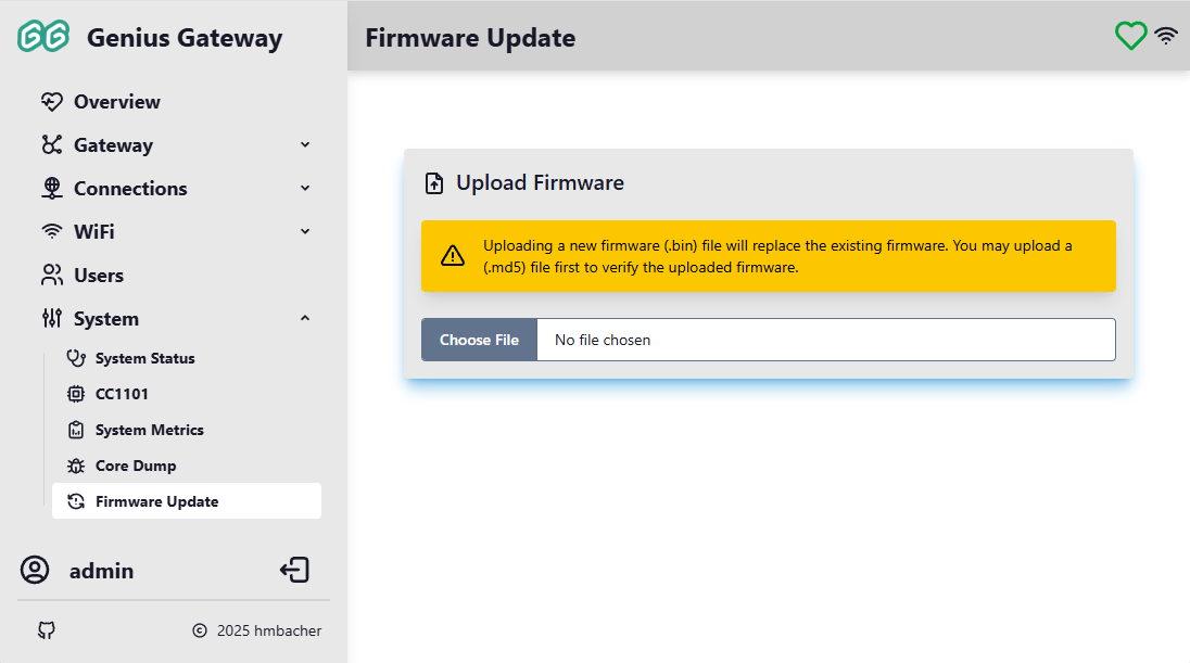
Upload Firmware
The Upload Firmware section allows manual installation of firmware files from your local computer.
Firmware Validation
The upload service performs several validation checks to ensure firmware safety:
- File Type Verification: Only
.bin(firmware binary) and.md5(checksum) files are accepted - Firmware Size Check: Minimum size of 1 MB required (for the
.binfile) to be recognized as valid firmware -
Target Hardware Validation: The firmware header is checked to ensure it matches the device's chip type (ESP32, ESP32-S2, ESP32-C3, or ESP32-S3)
Target Compatibility
Firmware compiled for a different ESP32 chip variant will be rejected during upload. For example, firmware built for ESP32-S3 cannot be uploaded to an ESP32-S2 device.
-
MD5 Checksum: If an
.md5file is uploaded before the firmware, the binary is verified against the checksum during upload
Supported File Types
- .bin: Compiled firmware binary file (minimum 1 MB)
- .md5: MD5 checksum file (32-character hex string)
The .md5 file should contain only the 32-character MD5 hash of the corresponding .bin file.
Uploading Firmware
To upload firmware manually:
-
(Optional) Upload MD5 checksum first:
- Click Choose File and select the
.md5file - The checksum is stored and will be used to verify the firmware
- Click Choose File and select the
-
Upload the firmware binary:
- Click Choose File and select the
.binfile - A confirmation dialog appears: "Are you sure you want to overwrite the existing firmware with a new one?"
- Click Upload to confirm and begin the installation
- Click Choose File and select the
-
Firmware Installation:
- The device validates the firmware header
- If an MD5 checksum was provided, the firmware is verified against it
- The firmware is written to the device's flash memory
- Upon successful completion, the device automatically restarts and executes the newly installed firmware
Failure Recovery
If the firmware validation or flashing fails or the device becomes unresponsive after an update:
- After upload: If validation fails (wrong chip type, MD5 mismatch), the upload is rejected and the current firmware remains active
- During flashing: If persisting the new firmware to flash memory fails, the current firmware remains active after restart
- After restart: If the new firmware crashes or fails to boot properly, the device will likely enter a boot loop. Then a manual recovery is required, i.e. flashing a working firmware via USB using the build and flash instructions.
No Automatic Rollback
The firmware does not implement automatic rollback to the previous version. Always test new firmware builds on a development device before updating production devices.